VAVincent Agbeibor

UNIVERSITY OF VIRGINIA / B.S. MECHANICAL ENGINEERING / MINOR: ENGINEERING BUSINESS

Engineering with
a human purpose.

I’m Vincent. I want to turn mechanical ideas into practical tools that help people.

MY WHY — AMANI MEDICAL FOUNDATION

Amani Medical Foundation began when I was a child. Since then, I have joined multiple medical mission trips to Ghana and taken part in the work of establishing a hospital for women and children. That experience gave my interest in engineering a purpose: I want to build things that help people receive better care.

Today, I support the foundation through medical-equipment research and website updates. As a mechanical engineering student at the University of Virginia, I am developing the design, prototyping, and testing skills I hope to bring to medical devices and healthcare technology.

University of Virginia / B.S. Mechanical Engineering / Minor: Engineering Business

Vincent Agbeibor outdoors wearing a white shirt
Vincent Agbeibor Mechanical Engineering · Class of 2028
DESIGN → BUILD → TEST → LEARN

SolidWorks · MATLAB · Prototyping · 3D printing · Instrumentation · Experimental testing · Manufacturing drawings · Technical documentation

SELECTED WORK / 01—03

Ideas made tangible.

Three projects connecting mechanical design, physical prototypes, and evidence from testing.

01

MECHANICAL DESIGN INTERNSHIP · UVA · SUMMER 2026

From static lab to dynamic system.

Compound gear-train teaching apparatus
SolidWorks3D printingMATLABPASCO

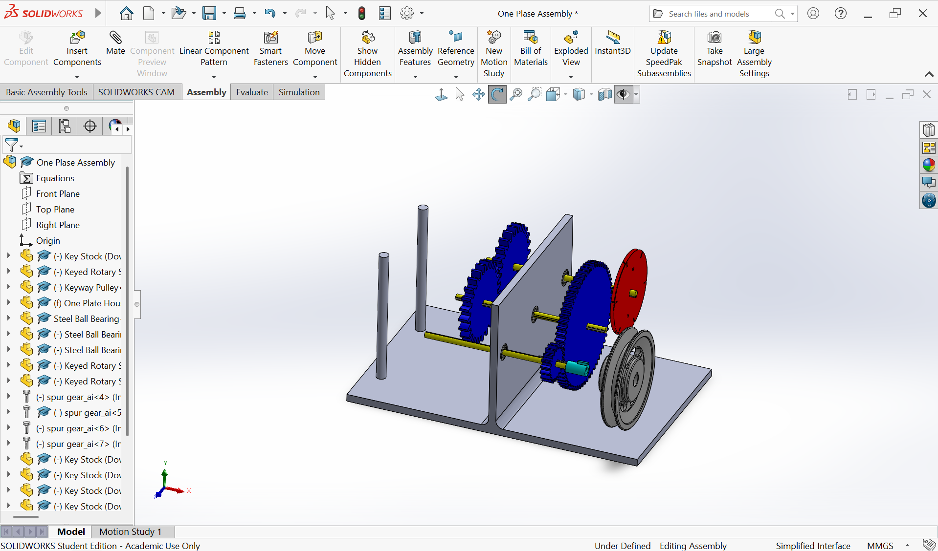
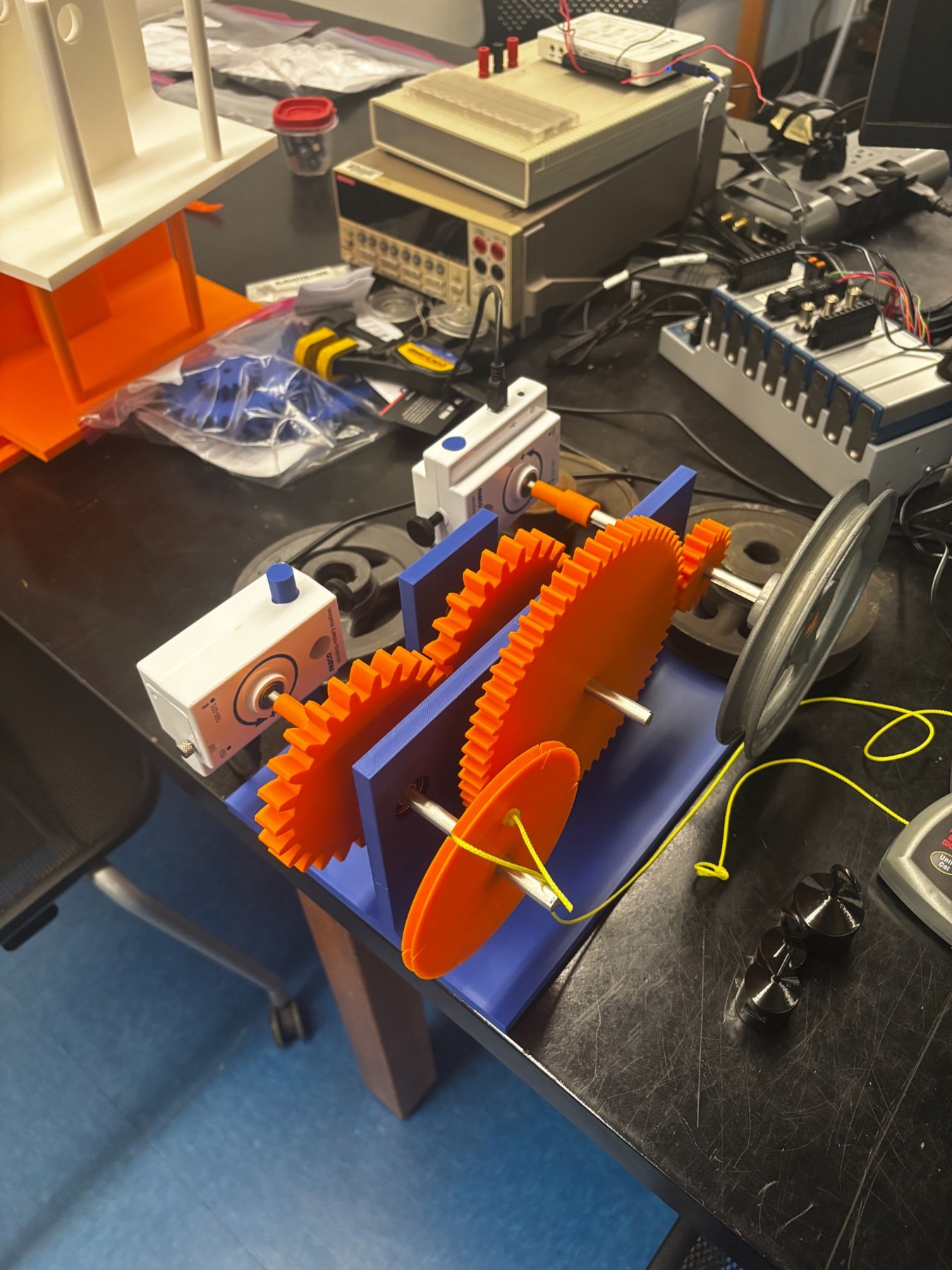
I developed a tabletop compound gear-train apparatus to extend a static teaching lab into a dynamic experiment. The system uses a falling mass, three shafts, four gears, and a flywheel to connect gear ratios with angular acceleration, torque, and power.

Individual project — full ownership

This was an individual project: I independently completed the research, CAD design, fabrication, prototyping, assembly, testing, MATLAB analysis, and technical documentation. I also authored the student lab manual for planned use by more than 100 students.

3 shafts / 4 gears

Three 100 g trials produced a mean measured ratio of about 3.545 versus 3.556 theoretical (approximately 0.3% difference). A later test series yielded an estimated 84.9% efficiency using the revised inertia-based method.

Explore the design process +
01

Choose a teachable mechanism

After evaluating a planetary gearbox, I moved to a compound train that was easier to assemble, reconfigure, and explain in a student-led lab.

02

Iterate the physical design

I refined keyed interfaces, bearing fits, frame stiffness, and shaft spacing. A clearance conflict reinforced the value of checking the full assembly before printing.

03

Test the model, not just the hardware

I used MATLAB to explore inertia and hanging-mass choices, then PASCO rotary sensors to compare input and output motion. I replaced a circular torque calculation with an isolated flywheel test to estimate output inertia.

What the evidence supports

These are bench-test results, not a full uncertainty study. Flywheel inertia assumptions and measured-versus-predicted acceleration remained areas for refinement.
02

TEAM DESIGN PROJECT · UVA · JAN–MAY 2025

Making paddle wear measurable.

Pickleball paddle pressure gauge

CADArduino / C++PrototypingClient collaboration

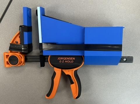
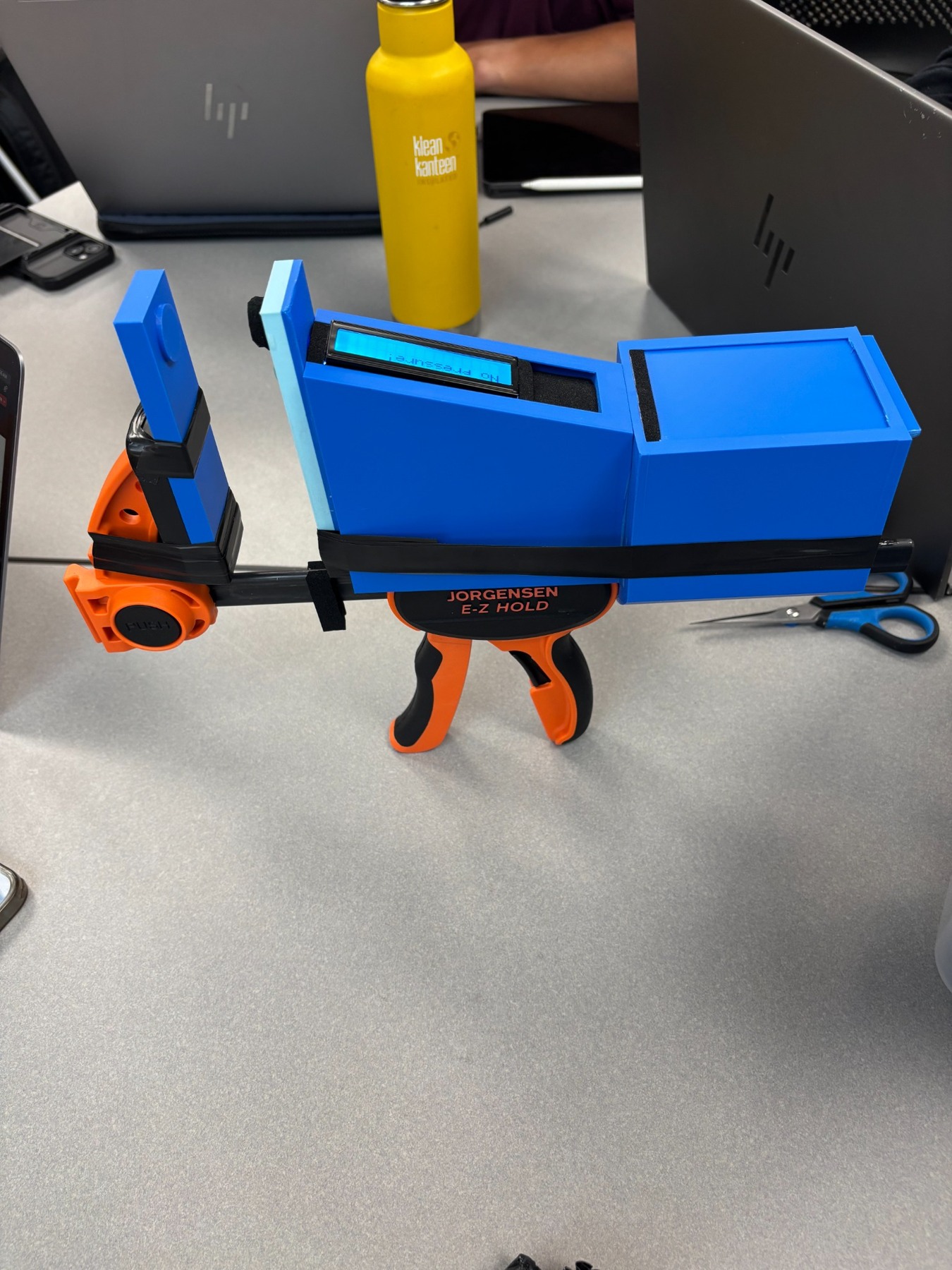
Our five-person team developed a portable clamp-based device to investigate pickleball paddle condition. By measuring resistance at the paddle’s sweet spot, we explored a repeatable way to compare new, used, and worn paddles.

My contribution

I designed CAD casing and clamp components, contributed to sensor-reading and display code, and helped test the device. I also worked with the team and client on design decisions, documentation, and the final presentation.

Top 7 of 157

The project placed in the top 7 of 157 engineering design projects at UVA. Our central technical finding was that a useful replacement threshold must account for paddle construction and model.

Explore the design process +
01

Translate the client’s problem

The client needed a practical way to assess wear hidden inside a paddle. Our constraints included a $500 budget, backpack portability, and a test procedure under five minutes.

02

Integrate the prototype

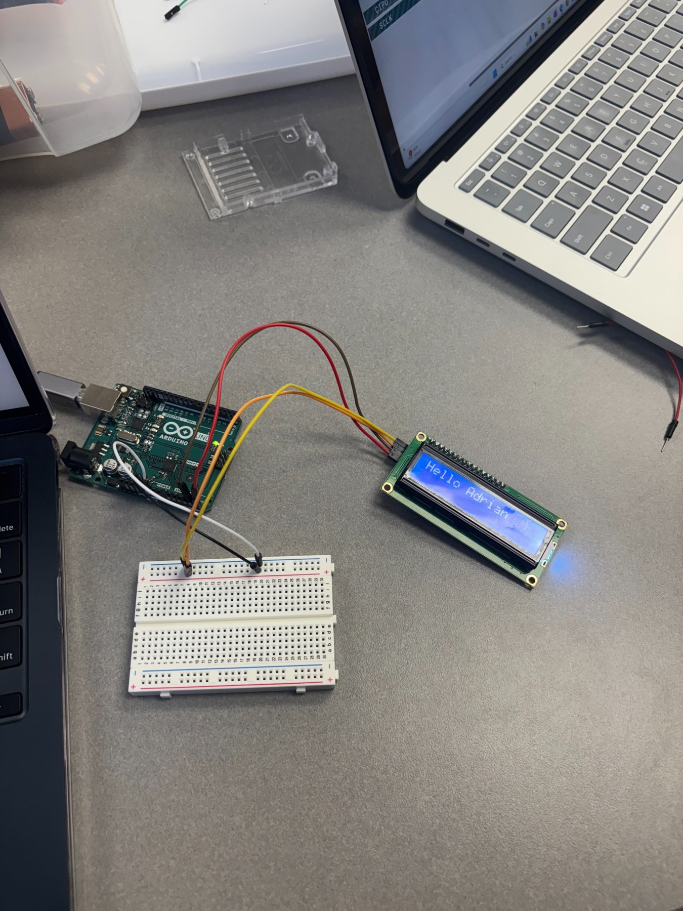
We combined a pressure sensor, Arduino, display, and modified clamp. Printed housings organized the electronics; revised geometry reduced material use.

03

Compare paddle conditions

I contributed to more than 50 tests across approximately five paddles. The team’s poster shows lower measured resistance for more worn Gonex paddles and different baselines across paddle types.

What the evidence supports

The prototype demonstrated comparative measurements; it did not establish a universal or independently validated end-of-life threshold. Broader calibration and controlled clamp loading are next steps.

03

CAVALIMBS · MECHANICAL DESIGN · FALL 2026 · IN PROGRESS

Exploring how a finger can grasp.

Prosthetic finger mechanism workshop

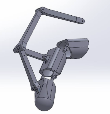
Prosthetic finger mechanism concept.
Mechanism designCAD3D printingTeam prototyping

As a member of CavaLIMBS, an engineering club at UVA, I apply my mechanical engineering skills to biomechanics by contributing to the development of prosthetic finger mechanisms. Mechanical teams are exploring different approaches before comparing which direction offers the most useful and practical grasping motion.

My contribution

My work focuses on mechanical design and printed prototyping, including component fit and tolerances. The current workshop is moving from individual phalanges toward joints and complete finger mechanisms.

Prototype development

Work is in progress. The workshop has established design guidelines and divided the concept work among teams; a final mechanism and validated performance results have not yet been selected.

Explore the design process +
01

Explore competing concepts

Teams are researching tendon-driven, linkage, and other mechanisms. Each mechanical group is responsible for CAD, fabrication, and assembly of its own concept.

02

Design around the details

Current guidelines emphasize documented finger dimensions, metric fasteners, print orientation, and tendon attachment. Two- and three-phalange concepts remain open for comparison.

03

Prepare to compare prototypes

The next step is to connect component designs into working mechanisms and compare grasping motion, manufacturability, and assembly. Electrical and sensing groups are developing actuator and control test setups.

LET’S BUILD SOMETHING USEFUL

Curious about the work?
I’d love to talk.

I’m interested in mechanical design, medical devices, and engineering that improves everyday life.